


Description
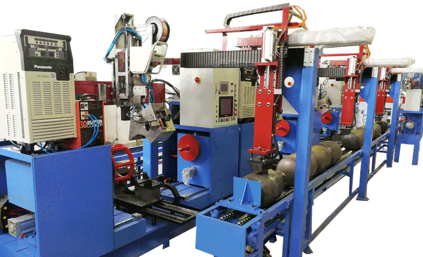
Hydraulic Decoiler&Blanking Line for LPG Cylinder Production Line
1. Function and features
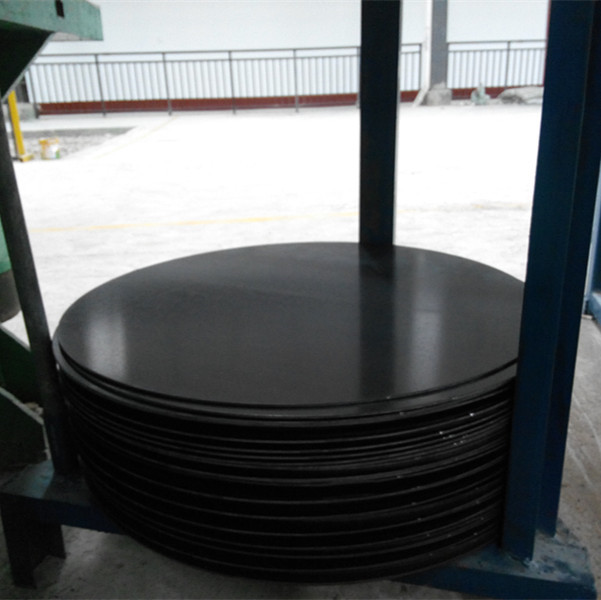
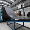
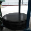
The automatic decoiler and blanking line is widely used in cylinder production line, from decoiler the strip coil to from the round sheet. That line combines the system both domestic and abroad, which can reach the international standard. The line has the features: compact structure, easy operation, safe operation etc, with independent motor system and electric system. Using buttons to centralized control the machine. Using PLC controller, the operation can be both inching and semi-auto.
2. Main parameters
Decoiler line
| No | Name | Unit | Parameter |
| 1 | Straightening Thickness | mm | 2-4 |
| 2 | Straightening Width | mm | 1000-1690 |
| 3 | No. of rolls | 9 | |
| 4 | Straightening Speed | m/min | 10-12 |
| 5 | Inner diameter of the coil | mm | 500-800 |
| 6 | Max. Outer diameter of the coil | mm | 2500 |
| 7 | Max. Weight of the coil | T | 40 |
| 8 | Center height | mm | 1000 |
| 9 | Motor power | KW | 30+1.5×3 |
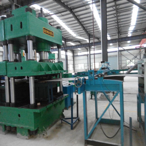
3. Main brief structure
The machine consists of machine main body, decoiler and straightening and blanking device, control system. Through the tubes and electric device, they will combine together into a whole part. The main machine includes the machine body, main cylinder, liquid filling equipment. The control system includes the hydraulic station(power system), electric cabinet and control board.
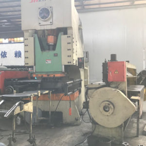
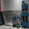
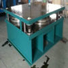
(1) Machine body(see shape figure)
Machine body consists of top beam, working table, slider, upright, jam nut, regulating nut. Depending on eight uprights, the top beam and the working table will be connected by jam nuts. The slider is installed between the top beam and working table. Through changing the regulation nut and lock net on the top beam, we can guarantee the machine accuracy. The slider will move up and down along with the four columns. There is T-slot on the slider and working table, which is easy for mould installation. The column is high quality 45# forging, oriented surface has been quenching treatment to improve the abrasive resistance.
(2) Main cylinder
The main cylinder is fixed in the top beam by cylinder end ledge and big lock net. The end of the piston will connect with the slider. The head of the piston is cast iron, working as a direction. On the outer round of the piston head, there is a opposite direction sealing, inside is the O-type sealing. It will form two oil chambers up and down. The lock net will tightly lock the the sealing on the mouth of the cylinder to ensure the sealing of the bottom oil chamber.
(3) Electric cabinet
The control cabinet can be freely moved in a definite range. On the electric cabinet, there are buttons and time relay. The auto air switch is installed on the left side.
(4) Lead limit switch
The lead limit switch is installed on the both sides of the machine body, consisting of supporter, striker, proximity switch. The two sides of the supporter are fixed on the working table and the right side of the top beam. The proximity switch is fixed on the supporter. Adjusting the position of the proximity switch can adjust the position of the slider.
(5) Hydraulic station(motor system)
Hydraulic station consists of the oil tank and motor. The oil tank welded by steel plate, inside is the filter screen. The oil pointer is used for observing the oil position. The height of the oil should be higher than the oil pointer, if lower, it needs to add the oil.
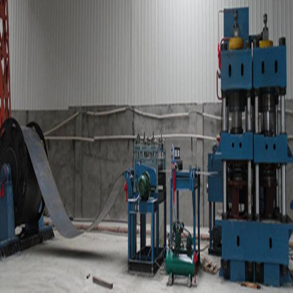
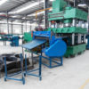
(6) Decoiler rack
It adopts welding structure. The decoiler consists of symmetric style internal-swelling material holder, symmetric guide rail type chassis, reducer, rack, decoiler spindle, material rack. There are left and right racks. One side is driven by motor to expanding the opening, so that easy to load the trip coil. Two sides have the fine tuning device to ensure the strip coil and the decoiler in center justification.
(7) Decoiler machine
The decoiler machine is driven by reducer and motor, using 9 straightening roller. From the decoiler machine to the material unloading side, there is side position limit device. The machine can achieve fixed-length feeding through rotary encoder.
4. Hydraulic system
Hydraulic system consists of power control system, all kinds of valves and hydraulic operation cabinet. Hydraulic system will provide the power and control the main machine. The hydraulic system is on the right side of the machine body.
4.1. Hydraulic system adopts the advanced cartridge valve integrated system with high flow, anti-pollution, flexible control, reliable performance and easy repairing.
4.2. Hydraulic system working pressure is 25Mpa, The main valve is two way cartridge valve and the hydraulic system has overload protection.
4.3. The oil tank is welding structure. Oil-level indicator and air filter are installed on the oil tank. When installing the oil tank, it needs acid pickling, passivation, rust-proof treatment. The oil filter will ensure the filter precision, which can guarantee the cleanness of the working oil. Also the machine is completely with jam alarm of the filter device.
4.4. The hydraulic tube system should be sealing and reliable. The connect way preferentially adopts flange connection. The tube arrangement is neat and orderly with anti-seismic tube clamps and shatter-proof pressure gauge. The tube line will be phosphating and then painted with anti-rust oil-proof painting. The oil tube cannot be exposed on the front of the machine.
4.5. Liquid filling valve: main function is to absorb and discharge the oil of the main cylinder. When the slider rapidly go down, the valve will turn on, many oil will enter the oil cylinder from the oil tank. When the slider stop moving, the valve will close under the effect of spring. When the slider go back, pressure release valve will open, discharge the oil to the oil tank.
4.6. To effectively control the leakage of the hydraulic system, we can do as follows:
4.6.1 The junction surface adopts high quality seal ring. Everywhere in the system should be in good sealing in case air coming in, effectively avoid the oil leakage.
4.6.2 The tube line should be neat and orderly. The high pressure tube and low pressure tube have different colors, adopting flange connection and enough shock isolation clamp. The tube line mostly uses integrated connections to avoid less leakage point.
5. Electric control system(motor part and control part)
5.1. Motor part: control the on/off and protection switch of the main power and each motor. High power motor adopts star-triangle start, which has small impulsion on the power network and has high anti=jamming capability.
5.2. Control part: main console and mobile operation table. The PLC controller is installed in main console, with all the operation buttons and function switch, on/off of the motor, alarm, monitoring and display. We can know the working condition of the hydraulic presser and control and finish all the operation of the machine. The electric cabinet has good sealing, can effectively avoid dust coming in. Also there is a mobile button station to operate manually.
6. Operation of the hydraulic presser
6.1. Two operation: inching and semi-automatic
6.2. The slider is adjusted by stoke control device.
6.3. The buttons can finish all the operations of the hydraulic presser, also have the button “two hands suppress”, “back swing”, “stop”, “emergency stop”.
7. Safety protection
7.1. Motionless and emergency stop button: When something special happens, press “motionless” to stop the hydraulic presser; when you press “emergency stop”, all will stop include the motors.
7.2. Overload protection: there is hydraulic safety valve in the hydraulic system to protect the hydraulic presser from damage.
7.3. There are limit switches on the top and bottom limit of the slider.
7.4. Requires two hands to operation the button.
7.5. In the bottom chamber of the piston-cylinder, there is hydraulic supporter insurance circuit.
8. Machine working environment
8.1. Power: 3 phrase 380V(±5%), 50Hz
8.2. Working temperature: 0~40℃
9. Main components
| No | Name | Supplier |
| 1 | Main hydraulic components | YWS or Jining Taifeng |
| 2 | High pressure oil pump | Beijing Huade or Qidong Gaoya |
| 3 | Motor | Shanghai Lichao or Jiangsu Dazhong Motor |
| 4 | Travel switch(no contact switch) | 0MRON |
| 5 | Host command button | Schneider |
| 6 | Pressure gauge | Wuxi |
| 7 | Control transformer | Chinese Zhengtai |
| 8 | A.C. contactor | OMRON, Siemens |
| 9 | Automatic air breaker | |
| 10 | Thermal relay | |
| 11 | Time relay | |
| 12 | Seal ring | AL-KO seal ring |
| 13 | PLC | Mitsubishi |
10. Technical profiles
10.1 Operation instruction
10.2 Machine qualification certificate
10.3 Packing list
10.4 Carried pares: sealing, special toolings and foundation bolts

FAQ
LPG cylinder manufacturing equipment
Q: What size of LPG cylinder your machine can produce?
A: 6kg, 12kg,15kgs and 50kgs LPG cylinder for cooking and other size according customers’ requirement.
Q: Can you design machines according LPG cylinder technical drawing?
A: Sure, please send your technical drawing to us.
Q: What are the benefits to choose your machines?
A: Our machines are strong and reliable for long term industrial manufacturing
To enable me give you correct proposal for correct machines, please tell me following details:
We need to know following information to quote you correct machineries:
1.Technical Drawing of the cylinders you want to make?
2.What size of cylinder you want to produce?(6kg, 12kg)
3.What diameter and thickness of the cylinder you want to make?
4.Are you new in this area or you already have some machines in the workshop?
5.Capacity you require, i.e. how many pieces and sizes you want to make per day?