


Description
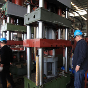
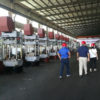
LPG Cylinder Deep Drawing Process Machine
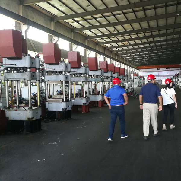
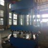
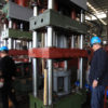
Usage and characteristics of hydraulic presser
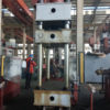
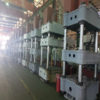
This machine is a four-column double-action hydraulic presser, which is suitable for the stretching and drawing of metal sheet.
With an independent power system and electrical system, this machine is under centralized control with buttons. It is controlled by PLC, so inching and semi-automatic operations can be realized.
Both the working pressure and stroke distance of this machine can be adjusted as per the technological needs.

1.Overview of machine structure and performance
The design of host machine absorbs the advantages of products of all main manufacturers at home and abroad and the essence of technical produces is introduced. Through the finite element optimization design and industrial design, the complete machine forms the amenity-oriented design style, which emphasizes the overall performance, practicability, durability, high strength and high reliability, and also highlights the modeling and color of the complete machine.
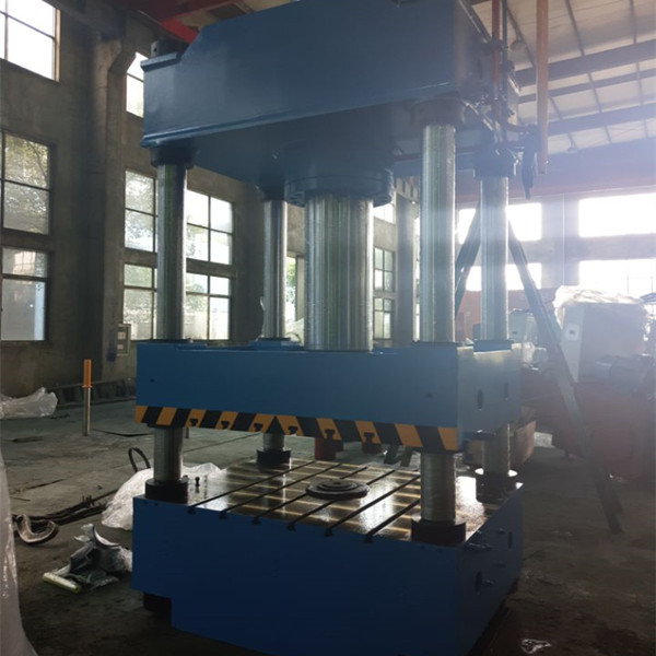
1.1 Machine body:
The body is composed of upper beam, stretching slider, blankholder slider, operating platform and upright etc. The upper beam and operating platform form a closed frame through the upright and nut. The body’s rigidity and precision retainability are good. The stretching slider and blankholder slider move upward and downward along the upright; the guide sleeve of upright is the composite copper sleeve to enhance the surface allowable pressure and reduce friction; the upright is made of 45# steel with quenching treatment on its surface.
The upper beam, stretching slider, blankholder slider and operating platform are of the steel plate-welded structure. After welding and high temperature annealing treatment, machining is finished. After polishing, there is neither welding slag nor scar in the weld joint so as to ensure the overall body is flat and beautiful in appearance, highly in accuracy and good in rigidity.
1.2 Oil cylinder:
The stretching oil cylinder uses a piston cylinder, which is installed inside the upper beam; besides, the cylinder body is fixed to the upper beam through flanges; the piston rod is connected to the stretching slider by the connecting flange.
The blankholder oil cylinder uses 6 piston cylinders, which are installed around the stretching oil cylinder. The cylinder body is fixed to the upper beam with flange; the piston rod is connected to the blankholder slider with the connecting flange.
The cylinder body is made of high-quality forged steel with uniform material quality; quenching treatment is conducted on the surfaces of all piston rods; oil cylinders will do high-voltage insulation test(1.1 times).
The oil cylinder is sealed with the imported sealing element so as to ensure the reliable sealing performance, no leakage and easy maintenance.
1.3 T-shaped slot
There are T-shaped slots on the operating platform, stretching slider and blankholder slider; the size of T-shaped slot is the standard size for the convenience of users’ mould installation.
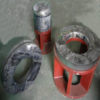
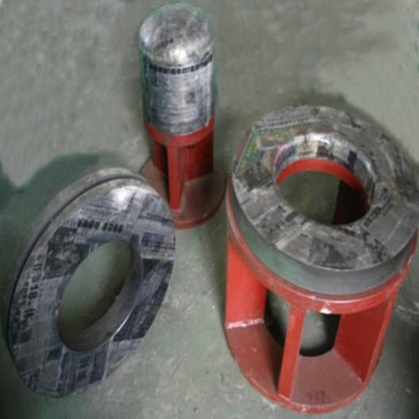
Deep drawing machine mould:
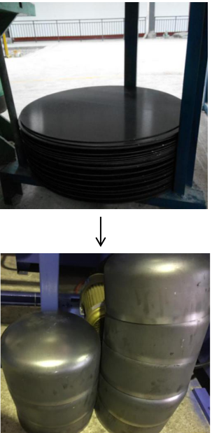
Cylinder head after deep drawing:
2.Electrical control system:
Electrical control: the electrical system consists of power part and control part.
2.1 Power part: It controls the main power as well as the start, stop and protection switch of all motors. The tri-star depressurized successively start up is used for the high-power motor. It has small impacts on power grid and strong antijamming capability.
2.2 Control part: the main control console and the moving button station. The main control console can complete the control and operation of all actions of the machine; with high leakproofness, the electrical box can effectively prevent dust invasion.
The main control console is equipped with the operating buttons and function switches of all actions of host machine, the start, stop, alarm, supervision and monitor display so that we can control the working condition of the hydraulic presser at any time.
The moving button station, which is used for the semi-automatic operating, is provided with the two-hand pressing button and emergency stop button etc.
3.Hydraulic part:
The hydraulic power system, which consists of power control system, all kinds of valves and hydraulic control box etc., provides power to the host machine and realize the control over host machine. The hydraulic system is installed on the right side of the machine body.
3.1 The hydraulic system uses the advanced integrated system of plug-in valve. The valve is characterized by high flow, anti-pollution, flexible control, reliable performance and easy maintenance.
3.2 The working pressure of hydraulic system is 25MPa. The high-pressure constant power variable oil pump is used as the main oil pump. The stretching cylinder and blankholder cylinder share one pump set and are distributed with flow reasonably according to the technological needs. The hydraulic system is equipped with an overload protection device.
3.3 The oil tank adopts a welding structure with steel plate, is equipped with oil level indicator and air filter etc. During installation, the oil tank shall undergo pickling, passivation and rust-proof treatment. Besides, the oil tank is equipped with an oil filter unit, the filter precision can guarantee the cleanliness of working oil; it can also realize blocking accident alarming of filter unit.
3.4 The hydraulic pipeline system shall be sealed and reliable; as for the connection type, the flange connection shall be preferred; the pipeline shall be arranged in order; besides, the anti-seismic pipe clamp and vibration-resisting pressure gauge shall be adopted; after phosphating, the pipeline shall be coated with rust-proof and oil-proof paint. It is not allowed to expose oil pipes in the front of host machine.
3.5 Description of prefill valve: the prefill valve is mainly used for oil absorption and discharge by the main cylinder. When the slider moves downward rapidly, the negative pressure formed in the upper chamber of main cylinder will open the prefill valve by absorbing and abundant oil in the oil tank will be filled into the oil cylinder; when the slider stops moving, the prefill valve will be closed under the action of spring force;
during the return stroke of slider, the control oil will open the pressure relief valve for pressure relief; then, the valve core is opened so that oil can be discharged towards the oil tank.
3.6 In order to effectively control the leakage of hydraulic system, the following measures are taken:
3.6.1 The faying surface (valve, valve block, flange, pipe connection) shall be sealed with the high-quality seal ring. All parts of the system shall be sealed reliably so as to avoid inclusion of air in the system and effectively prevent oil leakage of shell attachments and welding parts.
3.6.2 Pipes are arranged in order with distinct colors to differentiate high-pressure and low-pressure pipes. Flange connection shall be preferred. Besides, sufficient quakeproof and vibration-isolating pipe clamps are provided. Maximally use integrated connection to reduce the seepage points.
3.7 As for the cooling system, the cooling way with plate-type water cooler is adopted. It is stipulated that the allowable normal working oil pressure of press shall be greater than 10ºC and less than 60ºC. The demander shall provide water sources on its own (the temperature of cooling water shall be no more than 25ºC).
4.Operating mode of press
4.1 The press is provided with the inching and semi-automatic (two-hand single cycle) operations; the operations can be switched with the change-over switch and controlled concentratedly with buttons.
(1)Inching: A corresponding action will be started by pressing a certain working button and will be stopped by releasing the button; inching is mainly used for machine adjustment. This action cannot be fast.
(2)Semi-automatic (two-hand single cycle) operation: press the two-hand downward button, the press will continuously complete a specified single cycle process.
4.2 The holding time can be set by the time relay.
5.Safety protection measures for device
5.1 Static and emergency stop buttons: In case of any unusual conditions, press the “static” button and the work of press will be stopped completely; press the “emergency stop” button, and both the press and the motor will stop running.
5.2 Overload protection: It is required to provide the hydraulic relief valve in the hydraulic system so that the press won’t get damaged due to overload operation.
5.3 There are travel switches in the upstroke and downstroke extreme positions of slider.
5.4 There is a hydraulic supporting insurance loop in the lower chamber of main cylinder.
5.5 Buttons shall be operated with both hands.
5.6 There is a group of photo-electric safety devices in the front side of press, with the protection height of 600mm.
6.Equipment working condition:
6.1 voltage: three phase 380 v (±10%), 50 Hz
6.2 Working temperature: -5~40°C, humidity: maximum 80%
Equipment inspection standard
- Precision: According to GB/T 9166-2009 Precision four-column type hydraulic press
- Design and manufacture should according to related standard requests of hydraulic machines:
JB/T 3818-1999 Hydraulic machines technical specification
GB5226.1-2002 Mechanical safety – Mechanical electric device – part 1:general technical specification
JB/T 8609-1997 Metal forming machine welding technical specification
JB/T 3623-1984 Metal forming machine noise testing
File and Spare parts
1.Supply technical specification – 1
1.1 Equipment operating instruction
Including applications and features, mainly technical specification, structure summary, hydraulic system, electric device, installation and adjust, maintain, safety operating etc…
Insert images: general drawing, slider upward drawing, working table top drawing, structure drawings of all cylinders, hydraulic schematic diagram, electric schematic diagram, installation foundation drawing etc…
1.2 Certificate of conformity – 1
1.3 Packing list – 1
2. Spare parts (Expect the below items, the other installation tools will not be supplied within delivery)
2.1 All seals for all pipe ending – several
2.2 Bolt and nut for installation foundation plate – 1 set
FAQ
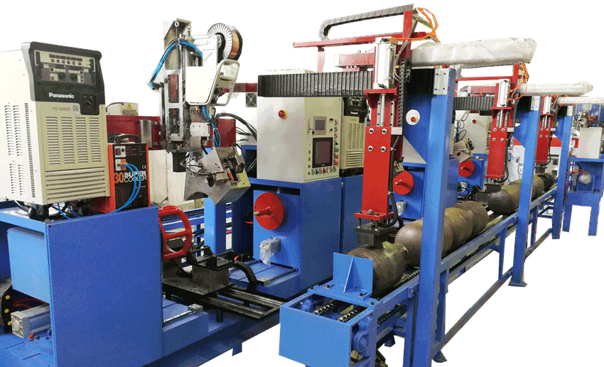
LPG cylinder manufacturing equipment
Q: What size of LPG cylinder your machine can produce?
A: 6kg, 12kg,15kgs and 50kgs LPG cylinder for cooking and other size according customers’ requirement.
Q: Can you design machines according LPG cylinder technical drawing?
A: Sure, please send your technical drawing to us.
Q: What are the benefits to choose your machines?
A: Our machines are strong and reliable for long term industrial manufacturing
To enable me give you correct proposal for correct machines, please tell me following details:
We need to know following information to quote you correct machineries:
1.Technical Drawing of the cylinders you want to make?
2.What size of cylinder you want to produce?(6kg, 12kg)
3.What diameter and thickness of the cylinder you want to make?
4.Are you new in this area or you already have some machines in the workshop?
5.Capacity you require, i.e. how many pieces and sizes you want to make per day?